Jekyll2026-07-07T13:15:44+00:00https://alvvalencia.github.io/feed.xmlÁlvaro ValenciaPortfolio and engineering log of Álvaro Valencia — Robotics Software Engineer at Auryn Robotics, Robotics Software Engineering graduate from URJC. SLAM, navigation, localization and embedded systems with ROS 2, Gazebo, C++ and Python.Álvaro Valencia MaiquezP6 — Visual Localization2025-12-22T09:00:00+00:002025-12-22T09:00:00+00:00https://alvvalencia.github.io/service-robotics/2025/12/22/P6-Visual-LocalizationVisual Localization and Navigation Using AprilTags
This project implements a vision-based localization and navigation system for a mobile robot using AprilTags as known references.
The robot continuously detects visual markers, estimates its global pose from the camera, and autonomously navigates towards them while avoiding frontal obstacles.
The system combines camera geometry, pose estimation, reactive control, and landmark-based localization, without relying on odometry or mapping.
General Strategy
The robot follows a main loop that integrates:
AprilTag detection using the onboard camera
Absolute pose estimation using known tag positions
Reactive obstacle avoidance using laser data
Navigation directed toward detected tags
Memory of visited landmarks
If no valid visual references are available, the robot performs a controlled rotation to recover localization.
AprilTag Map
Tag positions are defined a priori in a YAML file, each with:
(x, y, z) position
yaw orientation
These data are transformed into 4x4 homogeneous matrices, allowing direct transformations between the tag frame, the camera, and the world, establishing a global reference system.
Camera Model and Tag Geometry
The camera is modeled as a pinhole projection:
Square focal length proportional to the image width
Principal point at the center
No lens distortion
Each tag is defined as a square with known dimensions and its four local 3D points are stored, allowing pose estimation from a single image.
Visual Pose Estimation
For each detected tag:
Extract the corners from the image
Apply solvePnP to obtain the camera→tag transformation
Invert it to get tag→camera
Select the nearest tag to reduce noise
Compute the chain of transformations to the world
From this, we obtain:
Global pose (x, y)
yaw orientation of the camera’s forward axis
This provides an absolute pose estimate, independent of prior state.
Reference Frame Alignment
Fixed rotations are applied to align:
Camera forward direction
Horizontal world plane
Extracted yaw angle
This ensures a consistent geometric interpretation of position and orientation.
Reactive Obstacle Avoidance
The frontal sector is continuously monitored with the laser:
If a nearby obstacle is detected
And no tags are visible
The robot stops linear motion and rotates in place. The rotation direction depends on the obstacle location, enabling safe exploration while searching for visual references.
Landmark Selection
To avoid oscillations:
Detected tags are filtered using a memory of visited ones
Unvisited tags are prioritized
When approaching a tag, it is marked as visited
After each visit, the rotation direction can be reversed to improve coverage
Motion Control
A proportional controller is used toward the selected tag:
Linear velocity proportional to distance
Angular velocity proportional to orientation error
Commands are saturated to ensure smooth motion
If no valid pose estimate exists, the robot adopts cautious movement or a recovery rotation.
Pose Propagation
When no visual update is available, the estimated pose is propagated using differential kinematics.
Angular velocity is scaled to compensate for actuator mismatches, improving temporal consistency.
Videos
Non-Inverter
Inverter
Conclusion
This project demonstrates a complete landmark-based visual localization system:
Absolute pose estimation from tags
Robust recovery from reference loss
Reactive obstacle avoidance
Simple and effective navigation
Lightweight, modular, and suitable for indoor environments with visual markers
This work presents the design of an autonomous robot capable of exploring an unknown environment, continuously building a navigable map, and moving toward newly discovered targets using Breadth-First Search (BFS). The system integrates laser perception, dynamic map construction, reactive navigation, and automatic collision avoidance.
The goal is to achieve fully independent behavior where the robot identifies traversable areas, evaluates safety, generates local goals, and travels to them while actively avoiding nearby obstacles.
General Goal
The robot operates without predefined waypoints or prior maps.
Its mission is to:
Explore the environment while mapping obstacles in real time.
Identify safe regions distant from the robot and navigate toward them.
Avoid collisions and redirect its route when obstacles are detected.
Update the map and goal positions throughout the process.
This enables free exploration and progressive expansion of the mapped environment with no supervision.
Map Generation
The map is represented as an intensity grid:
Value
Meaning
0
obstacle detected
>0
free space, brighter = more frequently observed
The laser sensor reconstructs the environment through a full angular sweep:
Each ray advances in discrete steps, increasing intensity on free cells.
If an obstacle is detected, that cell is penalized by lowering intensity.
The map is updated only when the robot has moved sufficiently from its last recorded position, avoiding unnecessary recalculation of already explored areas.
The map is published to WebGUI as a user map viewable in real time.
The result is a continuous map where frequently observed areas appear brighter, and collision zones appear darker. The intensity updates use a logistic model to prevent saturation and allow gradual reinforcement of free space.
Intelligent Goal Selection
The navigation engine runs a radial BFS from the robot’s current position.
It searches for a cell that meets:
✔ safe minimum distance from the robot
✔ free region surrounding the target area
✔ unobstructed path from origin to goal
BFS returns two coordinates:
a mid target for smoother trajectory
a final target that optimally expands the exploration frontier
The robot moves toward the mid target first, then proceeds to the final target, gradually increasing the mapped region.
Motion Control
Movement relies on reactive orientation:
The relative angle between robot and target is computed.
If the angular error is high → rotation only.
If alignment is achieved → forward velocity is applied.
When half the route is completed, the goal automatically switches to the final target.
If the target area becomes unsafe, it is discarded and BFS selects a new one.
Active Obstacle Avoidance
A front-safety module ensures collision prevention:
If the laser detects a close obstacle within a narrow angular window, navigation is suspended and avoidance mode starts:
Stage
Action
phase 1 ~ rotation
in-place turn to open space
phase 2 ~ short forward motion
lateral escape from obstacle
phase 3
return to navigation mode
This sequence improves stability and provides fast reactions in confined areas. The duration of each phase is parametrizable to adapt to different environments.
Visualization
The interface displays:
the full map updated live
robot and targets highlighted as markers
exploration trail and processed goal points
This makes it easy to monitor exploration and understand how BFS drives spatial expansion.
Video
SLAM INTENSITY
SLAM PROBABILISTIC INTENSITY
Conclusion
This robot establishes a robust foundation for autonomous exploration and surveillance in unknown environments.
Its achieved capabilities include:
incremental laser-based mapping with continuous reconstruction
autonomous BFS-based target generation
reactive motion driven by angular error
immediate avoidance of close obstacles
The system is independent of prior maps or predefined routes, making it light, scalable, and suitable for real-world exploration and search applications.
This project presents the development of an autonomous robot system capable of navigating a warehouse environment, transporting shelves, and placing them in designated locations. The main goal is to combine path planning, precise motion control, and state-based task execution to achieve fully autonomous loading operations.
The system is designed to handle shelves of different sizes, avoid collisions, and interact with a simulated warehouse map to update the occupancy grid in real time.
General Strategy
The architecture integrates several modules:
Occupancy Map Handling: Processing warehouse maps, inflating obstacles, and adapting images for path planning.
Path Planning: Generating collision-free trajectories using the OMPL Reeds-Shepp planner, supporting forward and backward motion and minimum turning radius constraints.
Control and Navigation: Ackermann-style velocity and steering control to follow planned paths with precision.
Shelf Manipulation: Lifting and depositing shelves using virtual actuators, updating the occupancy map accordingly.
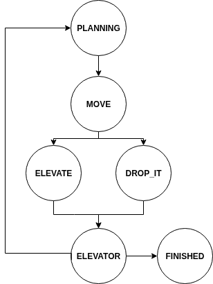
State Management: A finite state machine (FSM) coordinates planning, moving, elevating, dropping, and waiting stages.
Occupancy Map Processing
The robot relies on a map image of the warehouse. Several transformations are applied:
Map Inflation: Obstacles are expanded by the robot radius to ensure safe navigation, if it’s necessary.
Numpy Adaptation: The map is converted to numerical arrays for easy computation, where free space and obstacles are encoded with distinct intensity values.
Coordinate Transformations: Functions convert between world coordinates and map pixels, enabling accurate collision checks and path visualization.
Path Planning with OMPL
Collision-free paths are planned using Reeds-Shepp curves:
State Validity: Each state is checked for collision by evaluating the robot’s footprint or the shelf’s footprint if carrying a load.
Planner Setup: The robot space is bounded to the warehouse dimensions. Start and goal positions include x, y, and yaw coordinates.
Planner Execution: RRT* searches for an optimal path, interpolated for smooth execution.
Path Visualization: Planned paths are drawn on the map using lines and points, providing real-time feedback of trajectories.
Control and Motion
While moving along the path:
The robot computes the distance and angular error to the next waypoint.
Linear and angular velocities are adjusted using proportional control to reduce positional and heading errors.
Special alignment maneuvers are executed when approaching shelves to ensure precise pickup.
Motion parameters are adapted depending on whether the robot is carrying a shelf or not.
Shelf Manipulation
The robot performs two main operations with shelves:
Elevate (Pickup):
When the robot reaches a shelf position, it lifts the shelf using HAL.lift(), temporarily removes it from the occupancy map, and marks it as carried.
Drop (Deposit):
Upon reaching the target position, the shelf is placed using HAL.putdown(), and the occupancy map is updated to reflect the shelf’s new location.
A waiting time ensures the elevator mechanism completes its movement before resuming planning.
Finite State Machine
The robot’s behavior is coordinated by the following states:
PLANNING
Computes a new path to the current goal using the updated occupancy map.
MOVE
Follows the planned trajectory while correcting speed and heading, including special alignment for pickup points.
ELEVATE
Lifts the shelf from the floor and updates the map.
DROP_IT
Deposits the shelf at the target location, updating the occupancy map.
ELAVATOR
Waits for the lifting or dropping operation to finish before proceeding.
FINISHED
Indicates completion of all assigned transport tasks.
The FSM ensures robust sequencing of actions and allows the robot to autonomously cycle between multiple pickup and drop locations.
Visualization and Supervision
The WebGUI interface shows:
The current occupancy map with obstacles and shelves.
Planned paths with waypoints and traveled trajectories.
Updates in real time as shelves are moved, providing intuitive supervision of the robot’s operations.
Videos
Holonomic Robot
Ackermann Robot
Conclusions
The autonomous loading robot demonstrates effective integration of path planning, motion control, and task sequencing in a warehouse scenario.
Key achievements include:
Collision-free navigation in dynamic warehouse maps.
Autonomous pickup and deposition of shelves with precise positioning.
Real-time visualization of paths and occupancy updates.
Modular FSM design, making it easy to extend or modify tasks.
This system forms a foundation for future autonomous logistics solutions, capable of handling multiple transport goals with minimal supervision.
This project describes the implementation of a complete autonomous parking system applied to ground mobile robots. The main goal is to enable the robot to move through the environment, detect a free parking spot on its right side, align with it, and perform a full automatic parking maneuver with no human intervention.
The overall architecture combines laser–based perception, continuous reactive control over orientation, and a state machine responsible for selecting the correct behavior in each stage of the maneuver.
General Strategy
The system continuously reads data from the front, right, and rear laser sensors.
From these scans it performs:
Lateral correction and heading stabilization
Detection of available free space on the right side
Classification of lateral blocking context
State transitions based on geometric patterns
Control is executed by publishing linear and angular velocities through HAL.
Sensor Processing
Laser readings are filtered, infinite values are removed, and only valid useful ranges close to the robot are considered.
This allows conversion of raw scan data into relevant information such as:
Real lateral distance to obstacles
Frontal/rear proximity
Angular minimum patterns for geometric reasoning
Lateral Stabilization
While searching for a spot, the robot keeps a stable lateral distance to the side.
This is done by combining front, back and center-right differences to maintain a parallel trajectory relative to the street.
Environment Classification
Once the system detects a potential parking space on the right side of the robot, it analyzes the lateral context to determine which variant of parking maneuver should be executed.
The classification determines if on the right side there are vehicles:
In front of the parking gap
Behind the parking gap
On both sides of the parking gap
This allows the controller to choose the correct parking sequence variant, adapting steering direction and geometry to the scenario.
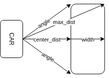
Gap Detection with Trigonometry
To verify if the parking gap is truly usable, the system checks whether a rectangle equivalent to the parking dimensions (PARKING_SIZE) could physically fit inside that space.
Using the lateral distance measured by the right laser, the controller calculates the angular region that represents the potential volume of the parking slot. Through trigonometric relations, the diagonal of that rectangle is obtained, representing the maximum spatial ray that should remain unobstructed. Si todas las lecturas dentro de ese rango angular son mayores que esta diagonal, significa que el robot puede entrar sin colisión.
Una vez que esta condición se cumple, el hueco se valida y se pasa a la fase de alineación.
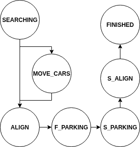
State Machine
The full maneuver is structured as:
SEARCHING
Drives forward while maintaining lateral regulation until a valid spot is found.
MOVE_CARS
Waits stable before starting alignment to allow external vehicle motion or scenario stabilization.
ALIGN
Initial alignment before starting the backup turn.
F_PARKING
First steering movement into the parking gap.
S_PARKING
Inverse steering correction finishing the “S” shape.
S_ALIGN
Final alignment phase inside the parking spot.
FINISHED
Parking completed.
All transitions depend exclusively on laser perception, no mapping, global navigation, or localization is required.
Test
The system also supports evaluation without depending on real scenario detection.
Through the internal variable test_env_ you can force manually which lateral scenario the robot believes it is in.
This allows testing each branch of the maneuver logic without needing to physically move cars inside the simulator:
[1,0] simulates a vehicle in front of the parking right side
[0,1] simulates a vehicle behind
[1,1] simulates vehicles both in front and behind the spot
This significantly accelerates functional testing and allows tuning before executing tests with realistic or more complex worlds.
Video
Both cars
Front car
Back car
Conclusion
This autonomous parking controller provides a practical and self–contained solution for parking in mobile robots.
Its reactive perception-driven architecture and state machine design enable robust behavior without complex planning systems.
Its lightweight structure is ideal for AGV applications, experimental urban robotics, and industrial autonomous navigation research.
]]>Álvaro Valencia MaiquezP2 — Rescue Drone2025-10-23T09:00:00+00:002025-10-23T09:00:00+00:00https://alvvalencia.github.io/service-robotics/2025/10/23/P2-Rescue-droneAutonomous Search and Rescue Drone
This project presents the implementation of an autonomous search and rescue system for a drone, designed to explore a defined area, locate people through computer vision, and automatically return to its base upon mission completion or under critical conditions.
The main objective is to ensure systematic and efficient exploration of the environment by combining geometric planning, flight control, and visual detection through image processing.
General Strategy
The system integrates several coordinated modules:
Path Planning: Generation of a square sweep trajectory over the search area.
Autonomous Flight Control: Waypoint tracking with position and orientation control.
Computer Vision: Human face detection using a cascade classifier.
State Management: Automatic transition between takeoff, exploration, return, and landing phases.
Temporal Supervision: Automatic return to the base point when the battery is depleted.
Sweep Planning
The search area is structured as a square defined by an initial coordinate, centered at the origin, and a lateral size.
The drone generates a set of evenly spaced waypoints covering the entire surface, alternating the exploration direction between rows to optimize the path and avoid unnecessary displacements.
The flight pattern ensures complete coverage with a constant altitude and an orientation angle calculated toward each new target. Each point is considered reached when the distance to the drone falls below a defined tolerance threshold.
Geographical Conversion
The coordinates of key points, such as the base ship position and the rescue zone, are defined in degrees, minutes, and seconds (DMS) format and converted into UTM distances, which are then transformed into Cartesian coordinates.
This conversion allows precise calculation of distances and directions using spherical trigonometry, taking the Earth’s radius as the reference.
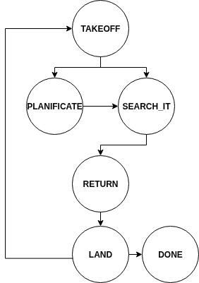
System States
The drone operates sequentially according to a defined set of states:
TAKEOFF
The drone takes off to a predefined operating altitude. Depending on the recharge status or if an interruption has been triggered, it proceeds to planning or resumes the search.
PLANIFICATE
The position of the rescue area is calculated from geographic coordinates, and the square exploration pattern is generated.
SEARCH_IT
The drone follows the planned trajectory. During flight, it analyzes images from its downward-facing camera to identify potential people using a face detection model.
Image rotations and HSV color-space filtering are applied to reduce false positives and improve robustness against lighting variations.
RETURN
Once the search is complete or the battery signal is triggered, the drone automatically returns to the base point, adjusting its orientation and flight path accordingly.
LAND
The drone initiates a controlled landing procedure. After verifying its position and maintaining stability for a minimum duration, the final landing is executed.
DONE
The mission concludes when the number of detected people reaches the predefined target or when the flight cycle is completed.
Person Detection
Human identification is performed using a Haar Cascade classifier trained for face detection.
During the search, the drone analyzes multiple image orientations to increase detection probability from different angles.
Each detection is validated against previously registered positions to avoid duplicates in nearby areas.
Detected positions are stored in an internal list associating the drone’s spatial coordinates with the locations where faces were identified.
Interruption Management and Automatic Return
The system includes a safety timer that limits mission duration to simulate battery depletion.
If the set time is exceeded or a critical event is detected, an interruption is triggered to force a transition to the return state.
This mechanism ensures the drone preserves enough battery to complete a safe landing.
Visualization and Supervision
During execution, the downward and front cameras are displayed in real time through the WebGUI interface, allowing monitoring of both navigation and human detection.
This visual system facilitates algorithm validation, drone behavior verification, and spatial coverage analysis.
Video
Conclusions
The search and rescue drone combines autonomous planning, flight control, computer vision, and real-time supervision to conduct exploration missions in bounded environments.
Its state-based architecture enhances system extensibility, allowing new conditions or sensors to be integrated without altering the main structure.
The integration of strategies such as sweep planning, automatic return, and multicriteria face detection forms a solid foundation for future applications in autonomous rescue and surveillance missions.
]]>Álvaro Valencia MaiquezP1 — Autonomous Vacuum Cleaner2025-10-12T09:00:00+00:002025-10-12T09:00:00+00:00https://alvvalencia.github.io/service-robotics/2025/10/12/P1-Autonomous-vacuum-cleanerAutonomous Navigation for a Vacuum Robot
In this blog, I present the implementation of a Grid-Based Planning & Navigation Algorithm for a vacuum robot. This system allows the robot to explore and clean an area efficiently, avoiding obstacles and optimizing surface coverage.
Strategy
The algorithm combines several techniques:
Obstacle Inflation 🚧: Increases the perceived size of obstacles to ensure the robot does not collide.
Grid Creation: The map is divided into cells classified by their state (free, occupied, obstacle, critical, or return).
Grid-Based Planning: A movement plan is generated from the starting cell to cover all accessible areas.
Robot Control: A proportional controller adjusts linear and angular velocity to follow the plan smoothly.
Initial Direction Selection: Based on laser data, the robot decides its initial orientation toward the area with the most free space.
Map Preparation
1. Obstacle Inflation
The map is inflated to increase obstacle size considering the robot’s radius, ensuring it does not get too close to walls or furniture.
2. NumPy Conversion
The map is converted into a NumPy array for easier processing, representing free and occupied cells with discrete values.
3. Grid Creation
The grid divides the map into cells roughly the size of the robot’s diameter. Each cell is classified as:
FREE: Accessible cell.
OBSTACLE: Cell occupied by an obstacle.
CLOSED: Partially accessible cell.
OCCUPIED: Already visited cell.
CRITICAL: Currently targeted cell.
RETURNED: Return cell to follow unexplored paths.
Each cell stores its center in pixels and its state, facilitating planning and visualization.
Motion Planning
1. Selecting the Initial Cell
The robot’s current cell is identified using its world coordinates and a map-to-pixels transformation function.
2. Priority and Exploration Order
The algorithm explores neighboring cells following a Dynamic Priority Order adjustable in real time. By default, it may follow West → North → East → South, but it can be modified depending on the environment or user preferences.
Each visited cell is marked as OCCUPIED. This dynamic priority is passed directly to the planificate_grid function, allowing the robot to change its exploration strategy based on specific needs or sensor data.
3. Searching for the Nearest Free Cell
If the robot gets stuck, BFS (Breadth-First Search) is used to find the nearest free cell. This ensures the robot continues exploring the entire area without getting trapped.
4. Plan Generation
The final plan consists of a list of cells the robot must visit, prioritizing full coverage while avoiding obstacles.
Robot Control
The robot adjusts its linear & angular velocity using a proportional controller that considers:
Distance to the target.
Angular error between the robot’s orientation and the target cell direction.
Alignment of upcoming cells to smooth or accelerate movement.
Speed reduction when approaching the target cell.
Maximum speed is limited for safety, and adjustment factors are applied to keep the robot aligned with the planned trajectory.
Initial Direction Based on Laser
Before starting, the laser data is analyzed to select the initial direction with the most free space. This avoids unnecessary movement toward blocked areas at the beginning of the route.
Robot States 🤖
The algorithm defines three main states:
PLANIFICATE 🗺️: Generates the exploration plan based on the grid.
TRAVEL_IT 🚶: Robot follows the plan visiting cells.
FINISHED ✅: All accessible cells have been explored.
TEST 🧪: Allows visual verification of the grid and the robot’s current position without moving.
Visualization and Monitoring
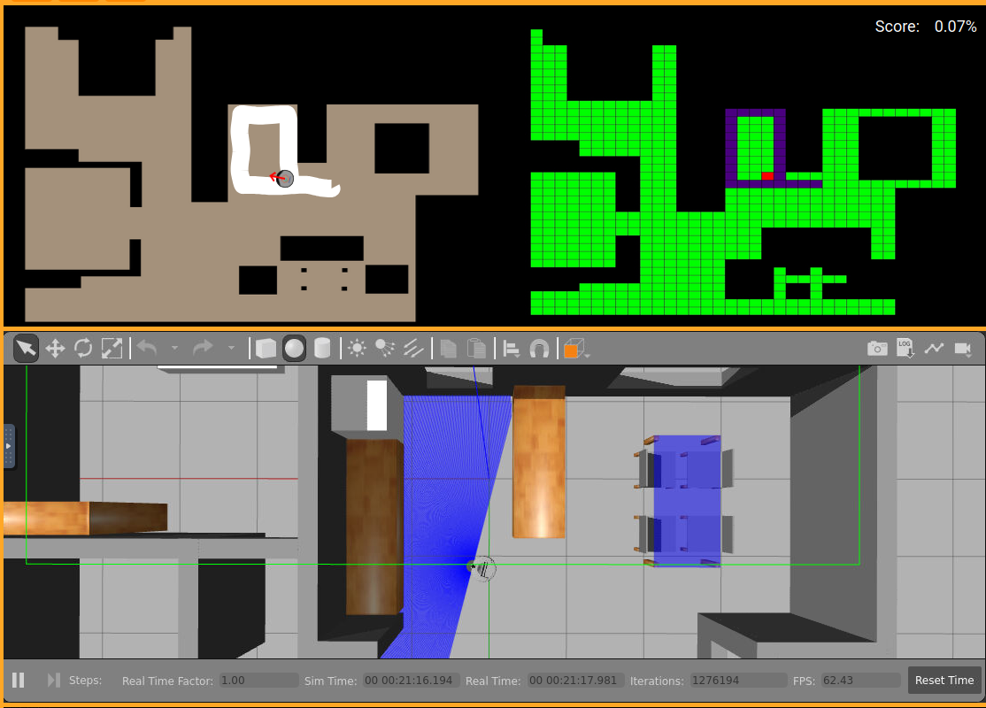
The grid and map are visualized in real time using WebGUI, with different colors according to each cell’s state:
Black: Obstacle
Green: Free
Indigo: Occupied
Red: Critical
Violet: Return
Orange: Default/Closed
This enables intuitive monitoring of the robot’s planning and progress.
Videos
Autonomous Cleaner 🤖:
Conclusion
This grid-based navigation system allows a vacuum robot to:
Explore complex areas autonomously.
Avoid obstacles and minimize collisions.
Efficiently cover the entire map surface.
Thanks to the combination of Obstacle Inflation 🚧, Grid Planning 🟩, BFS for Alternative Routes 🔍, and a Proportional Controller ⚙️, the robot achieves full and safe autonomous cleaning. This approach is scalable and can adapt to different environments by simply adjusting the grid size and the robot’s radius.
]]>Álvaro Valencia MaiquezROS 2 Rover2025-05-01T08:00:00+00:002025-05-01T08:00:00+00:00https://alvvalencia.github.io/modelating-simulation/2025/05/01/ROS2-RoverModelating Rover on ROS 2
Este proyecto se basa en la creación y modelación de un Rover en ROS 2.
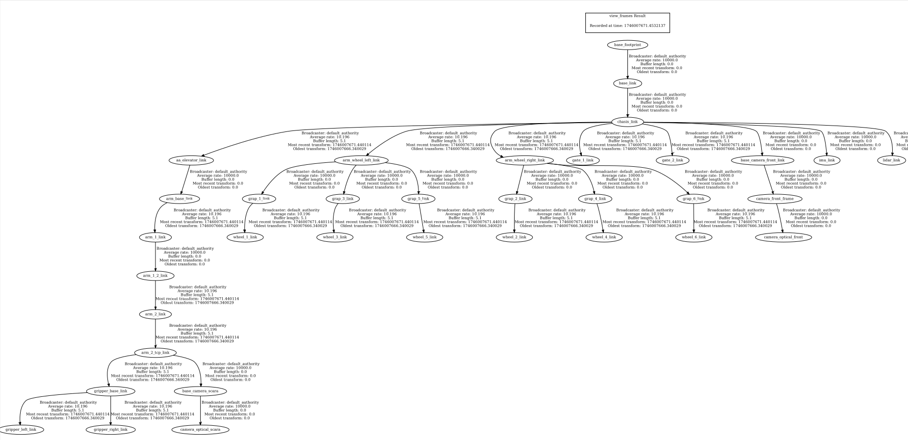
En una primera fase se realizó la modelación del Rover en Blender, para su posterior adición a Gazebo y su control mediante ROS 2.
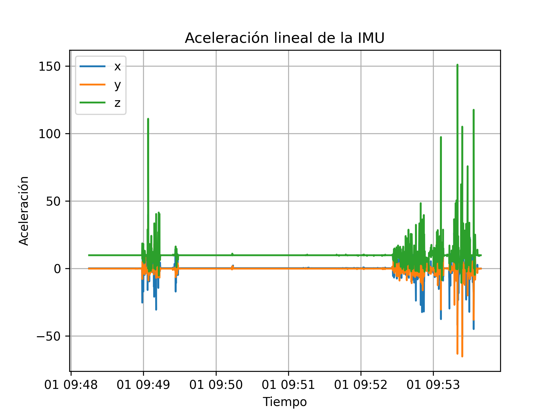
Aquí se puede ver cómo cambia la aceleración del rover a lo largo del movimiento. Al principio los valores son bastante estables, pero en el momento en que el rover se mueve hacia atrás y hace maniobras para posicionarse, empiezan a aparecer picos. Los picos más grandes se ven cuando el robot avanza con el cubo ya dentro, que es cuando más se nota el peso y los pequeños baches o ajustes del terreno.
Se nota totalmente, cuando el robot esta parado y solamente le influyen las fuerzas correspondientes a las físicas, como por ejemplo la gravedad en el eje z.
Grafo De Posicion
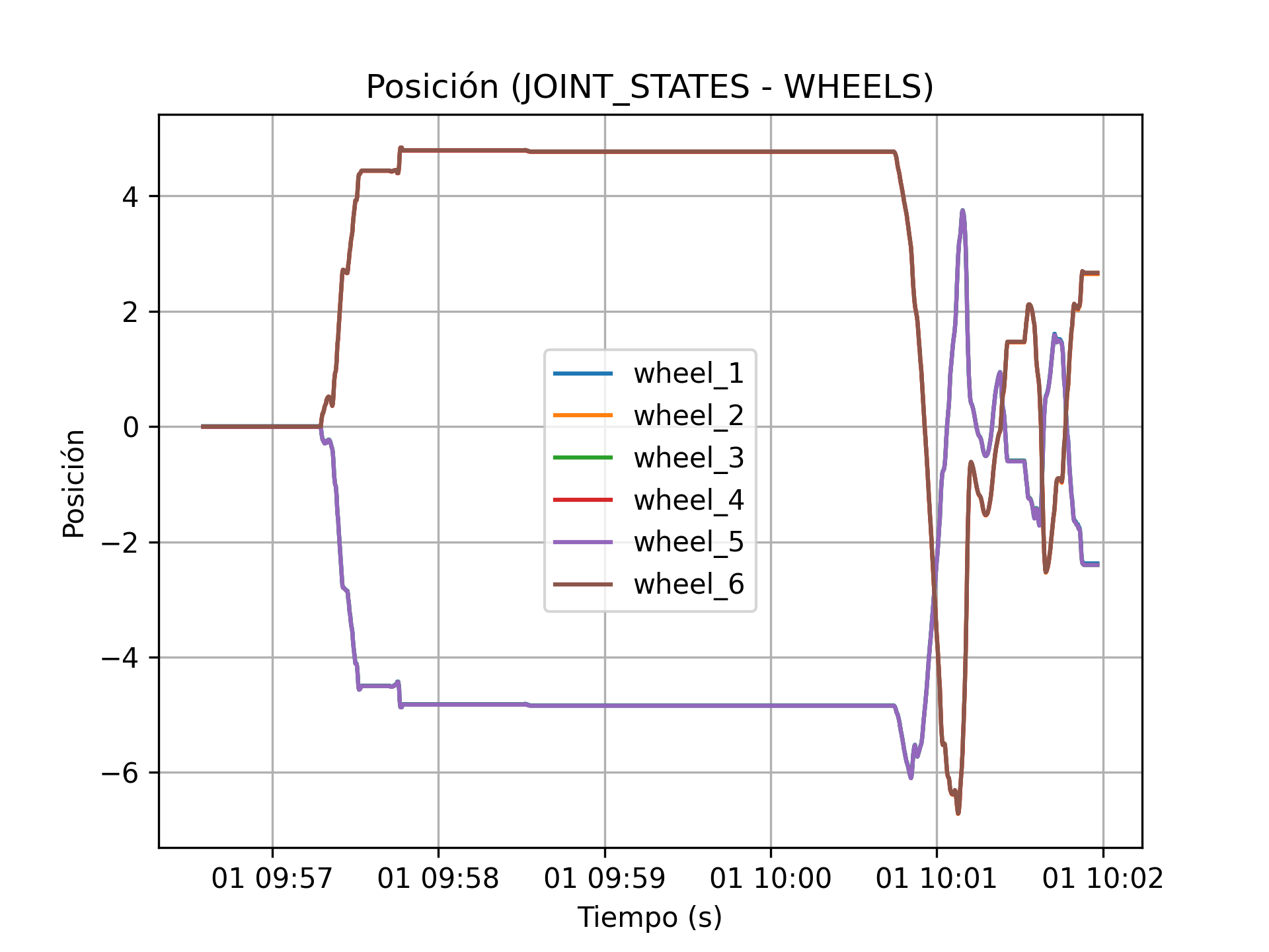
En esta gráfica se refleja claramente cuándo el rover da marcha atrás y luego empieza a moverse con el cubo ya dentro. Algunas ruedas tienen más movimiento que otras, debido a las pequeñas correcciones para posicionar el scara encima del cubo, y después para salir del sitio.
Grafo De Gasto
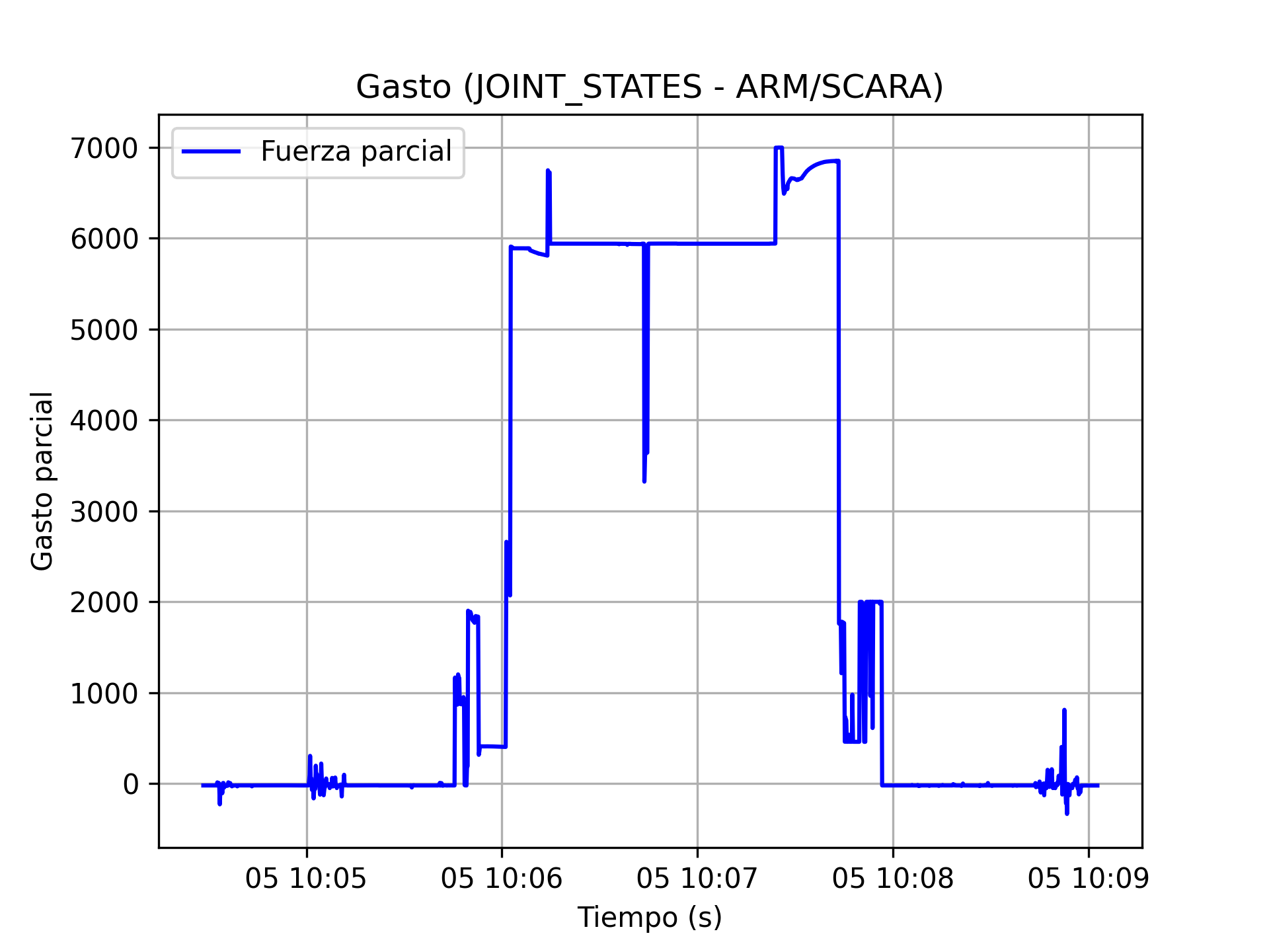
En este gráfico se observa claramente el comportamiento del brazo SCARA durante una tarea de manipulación, reflejado en el gasto parcial (asociado a la fuerza en las articulaciones).
Al inicio, el valor es bajo y estable, indicando que el brazo aún no ha comenzado a interactuar físicamente con el entorno.
Luego, hay un primer aumento de fuerza, que corresponde al momento en que el brazo se mueve hacia atrás para posicionarse y alinearse sobre el cubo.
A partir de ahí, se observa un pico más pronunciado: esto coincide con el descenso del brazo hacia el cubo. La fuerza aumenta al encontrarse con resistencia al hacer contacto con el objeto.
Posteriormente, se mantiene una fuerza elevada y algo estable. Esta fase representa cuando el brazo sostiene el cubo, manteniendo la pinza cerrada mientras se eleva y lo transporta hacia el compartimento de destino.
A mitad del gráfico se nota una ligera caída temporal en la fuerza, lo que se puede asociar a un momento de menor esfuerzo, probablemente al finalizar el levantamiento o en un punto de movimiento más controlado y suave.
Finalmente, se observa otro pico cuando el brazo desciende para colocar el cubo. La fuerza vuelve a aumentar al soltar el objeto, y luego cae bruscamente cuando finaliza la acción y el brazo queda en reposo.
En esta práctica se ha realizado la integración del robot en Gazebo y su control mediante ROS 2. Además, se ha simulado una tarea de recogida y transporte de un objeto utilizando un brazo SCARA, analizando el comportamiento del sistema a través de gráficas de aceleración, posición y esfuerzo.
Este proyecto describe el desarrollo de un coche seguidor de línea equipado con sensores infrarrojos y comunicación MQTT mediante un ESP32. El Arduino controla los motores y lee los sensores, mientras que el ESP32 recibe la información por puerto serie y la retransmite a un servidor MQTT para monitoreo remoto.
Componentes Utilizados
Sensores infrarrojos: Detectan la línea mediante valores analógicos.
Motores de corriente continua (DC): Controlados mediante señales analógicas PWM para ajustar velocidad y dirección.
ESP32: Encargado de la comunicación WiFi y MQTT.
Arduino UNO: Procesa los datos de los sensores y controla los motores.
LED RGB: Proporciona retroalimentación visual sobre el estado del sistema.
Sensor ultrasónico (HC-SR04): Detecta obstáculos en el camino.
Detección de Línea con Sensores Infrarrojos
Los sensores infrarrojos detectan la intensidad de luz reflejada, proporcionando un valor analógico. Este valor se compara con un umbral predefinido para determinar si el sensor está sobre la línea o fuera de ella.
Configuración de Sensores:
Left: A2
Mid: A1
Right: A0
Se define un umbral (VALUE_LINE) que determina si el valor leído está dentro del rango esperado para la línea. Este valor puede ajustarse experimentalmente según el entorno de operación.
Control de Motores
El sistema utiliza un control proporcional-derivativo (PD) para ajustar la velocidad de los motores en función del error calculado.
Errores y Corrección:
El error se basa en la diferencia entre los sensores laterales (izquierda y derecha).
Fórmula del error: error = (valor_derecha - valor_izquierda).
Se aplica una corrección proporcional definida en los parametros KP y KD.
Control de Velocidad:
La velocidad de los motores se ajusta usando analogWrite para generar señales PWM, permitiendo un control suave y preciso. Por ejemplo:
Un sensor ultrasónico detecta obstáculos y detiene el coche si la distancia detectada es inferior a un umbral seguro. Además, se envían mensajes de estado al ESP32, que posteriormente los retransmite al servidor MQTT.
La comunicación entre el Arduino y el ESP32 se realiza mediante el puerto serie. El Arduino envía información en formato JSON al ESP32, que posteriormente la envía a un servidor MQTT.
Proceso de Comunicación:
Arduino:
Envía mensajes JSON como:
{"line": 1} para pérdida de línea.
{"obst": distancia} para obstáculos.
ESP32:
Recibe los mensajes del Arduino por el puerto serie.
Los retransmite al servidor MQTT mediante el protocolo de publicación y suscripción.
Procesa los datos para monitoreo y control remoto.
Indicadores LED RGB
Los LEDs RGB proporcionan retroalimentación visual en tiempo real:
Verde: Sobre la línea.
Rojo: Fuera de la línea.
Especificaciones del código
En este proyecto, no se ha utilizado FreeRTOS por varias razones. A pesar de que el Arduino UNO es compatible con este sistema operativo, el proyecto no requiere un manejo complejo de múltiples tareas concurrentes. La funcionalidad principal del coche seguidor de línea (lectura de sensores, control de motores, y comunicación MQTT) se puede gestionar de manera eficiente utilizando un único hilo de ejecución en el Arduino y en el ESP32. Si que tenemos tareas con prioridades especificas como el hecho
de asegurarnos de publicar cada 4s un ping, pero el hecho de que incorporar FreeRTOS conlleva una perdida de un 20-30% del computo hace que no sea tan prescindible. Creemos que con un buen PD, o cualquier controlador optimo para el sistema, hará que las vueltas sean las más rápidas.
Arduino:
El código de control de motores y sensores se ejecuta en un bucle principal sin necesidad de un sistema operativo en tiempo real.
El procesamiento de los valores de los sensores y el ajuste de la velocidad de los motores se realiza en condiciones dentro del bucle principal, lo cual es suficiente para garantizar un control preciso y oportuno.
Se usa dos condicionantes principales que marcan si estás dentro de la linea o, totalmente perdido. Sinónimo de In Line o Search Line.
El sensor ultrasónico tiene un thread asociado que se llama cada 12ms, que realiza una toma de medición, accediendo a el mediante ultraSound->getDistance().
El ping está incorporado dentro de un thread llamado cada 4000ms.
El código esta totalmente pensado para si detecta un obstáculo pararse y mandar todo lo relacionado con END_LAP, pero si quitamos el obstáculo se vuelve a hacer otra vuelta nueva.
ESP32:
La comunicación entre el Arduino y el ESP32 se maneja mediante el puerto serie y para ello no se requiere la complejidad de FreeRTOS.
El ESP32 utiliza su capacidad WiFi para enviar los datos a un servidor MQTT, gestionando de manera eficiente la conexión y retransmisión de mensajes.
Video
Conclusión
Este sistema combina detección de líneas mediante sensores infrarrojos, control PD para precisión en el movimiento y comunicación MQTT para supervisión remota. La integración entre Arduino y ESP32 garantiza un sistema eficiente y escalable para futuras mejoras. El sistema es adaptable y permite la incorporación de nuevas funciones como seguimiento de múltiples rutas, reconocimiento de patrones y control por voz.
]]>Álvaro Valencia MaiquezP5 — Monte Carlo Localization2024-12-21T07:30:00+00:002024-12-21T07:30:00+00:00https://alvvalencia.github.io/mobile-robotics/2024/12/21/P5-monte-carlo-localizationMonte Carlo Localization (MCL)
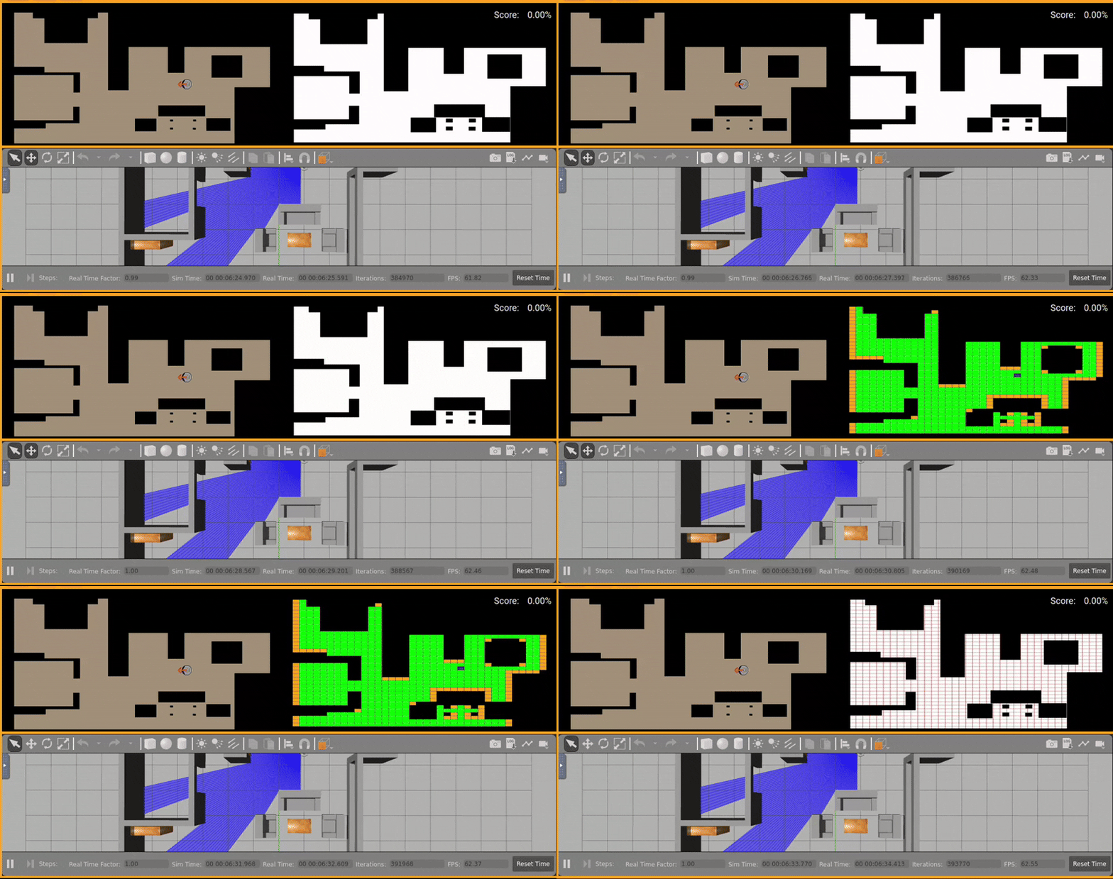
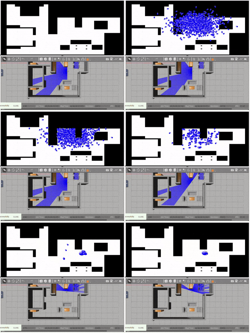
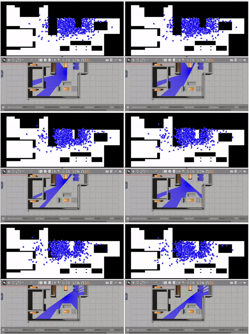
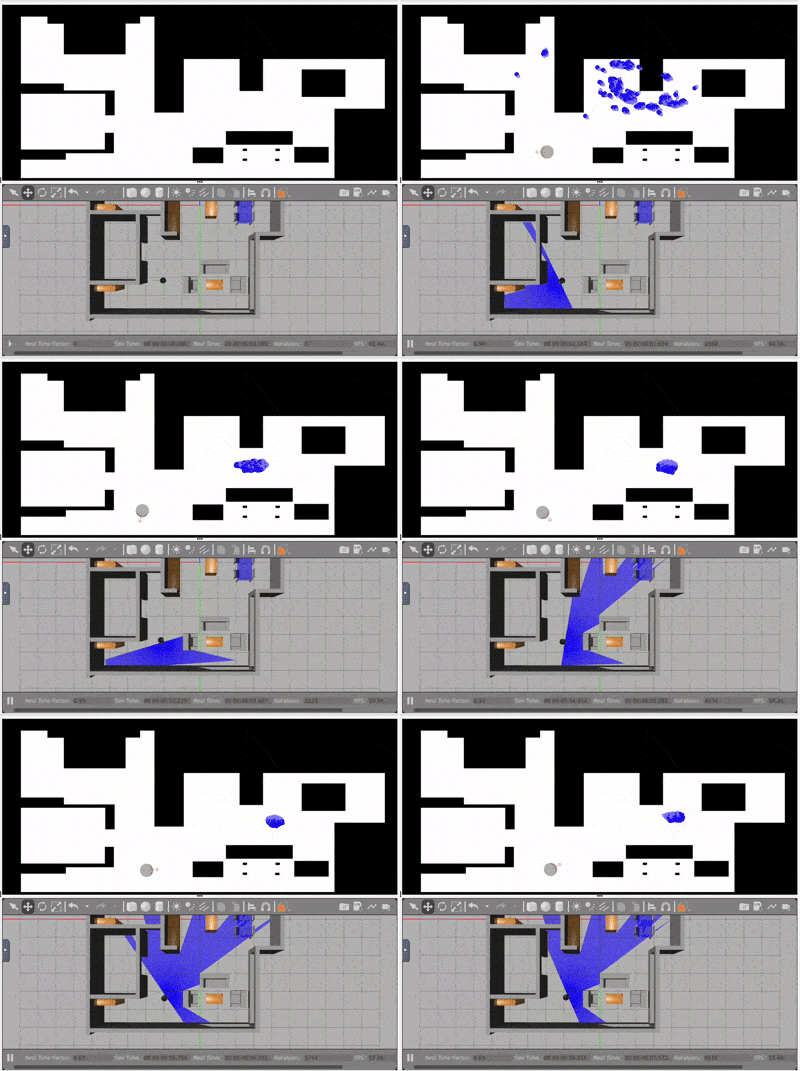
Monte Carlo Localization (MCL) is a probabilistic algorithm used for estimating the position and orientation of a mobile robot within a known map. It employs a particle filter approach, which models the robot’s location using a set of particles distributed across the map. Each particle represents a hypothesis about the robot’s state, and these hypotheses are iteratively refined as the robot moves and receives sensor data.
1. Particle Initialization
The algorithm begins by generating particles randomly distributed within the map. These particles represent possible initial positions and orientations of the robot. Gaussian noise is applied to each particle to simulate uncertainty, ensuring the robot’s position and orientation are likely represented by one of the particles.
2. Motion Update (Propagation)
As the robot moves, the particles are updated based on the motion commands. Random noise is added to account for slippage, wheel errors, and other sources of inaccuracy. This step ensures that the particle distribution reflects the robot’s movement with realistic deviations.
3. Sensor Update
For each particle, simulated sensor readings are compared to actual sensor measurements. This comparison helps determine how likely each particle is to represent the robot’s true position. Particles that closely match the real sensor data are assigned higher weights.
Probability formula:
4. Resampling
Particles are resampled based on their weights, giving preference to the most likely hypotheses. Low-probability particles are discarded, while high-probability particles are duplicated. This step effectively concentrates the particles around the areas where the robot is most likely located.
5. Visualization
Particles are displayed visually, providing a real-time graphical representation of the robot’s position estimate. This visualization aids in debugging and helps validate the algorithm’s performance.
Why Use MCL?
MCL is particularly useful because it handles uncertainty effectively and adapts dynamically to the robot’s movements and sensor readings. It is suitable for both static and dynamic environments, making it a versatile approach for mobile robot localization.
Challenges and Limitations
Despite its strengths, MCL also has some limitations:
Dependence on an Accurate Map:
The algorithm assumes the map is precise. Errors in the map can lead to localization failures.
Particle Count Trade-off:
Using too few particles may produce poor estimates, while too many particles can increase computational costs.
Sensor Noise Sensitivity:
Noisy sensor data can degrade performance if not properly modeled.
Parameter Tuning
To optimize performance, several parameters were fine-tuned:
Number of Particles: 1,000 particles were used to balance accuracy and computational efficiency.
Initial Uncertainty: Gaussian noise was applied to both position and orientation to simulate realistic uncertainty at startup.
Motion Noise: Small random variations were introduced during propagation to account for robot dynamics.
Sensor Noise: Probabilistic models were used to handle noisy sensor data and improve robustness.
Roulette Wheel Noise:
To ensure diversity during the resampling phase, Gaussian noise was added to the particles selected by the roulette wheel algorithm. This prevents particle depletion and avoids excessive clustering, particularly in environments with ambiguous sensor data or multiple hypotheses.
Multiprocessing for Virtual Laser Computation:
To improve computational efficiency, multiprocessing was utilized for the computation of virtual laser scans. Each particle’s sensor measurement was calculated in parallel, leveraging multiple CPU cores. This reduced processing time, enabling real-time performance even with high particle counts.
Videos
MCL:
Conclusion
The Monte Carlo Localization algorithm implemented in this project successfully estimates the robot’s position using a particle filter approach. Through careful parameter tuning and noise modeling, the algorithm achieves reliable performance even in the presence of sensor and motion uncertainties. Future improvements could include adaptive particle counts and integration with SLAM techniques for unknown environments.
]]>Álvaro Valencia MaiquezP3 — Vending Machine2024-11-30T10:10:00+00:002024-11-30T10:10:00+00:00https://alvvalencia.github.io/sistemas-empotrados/2024/11/30/Vending-machineMaquina Expendedora En Arduino UNO
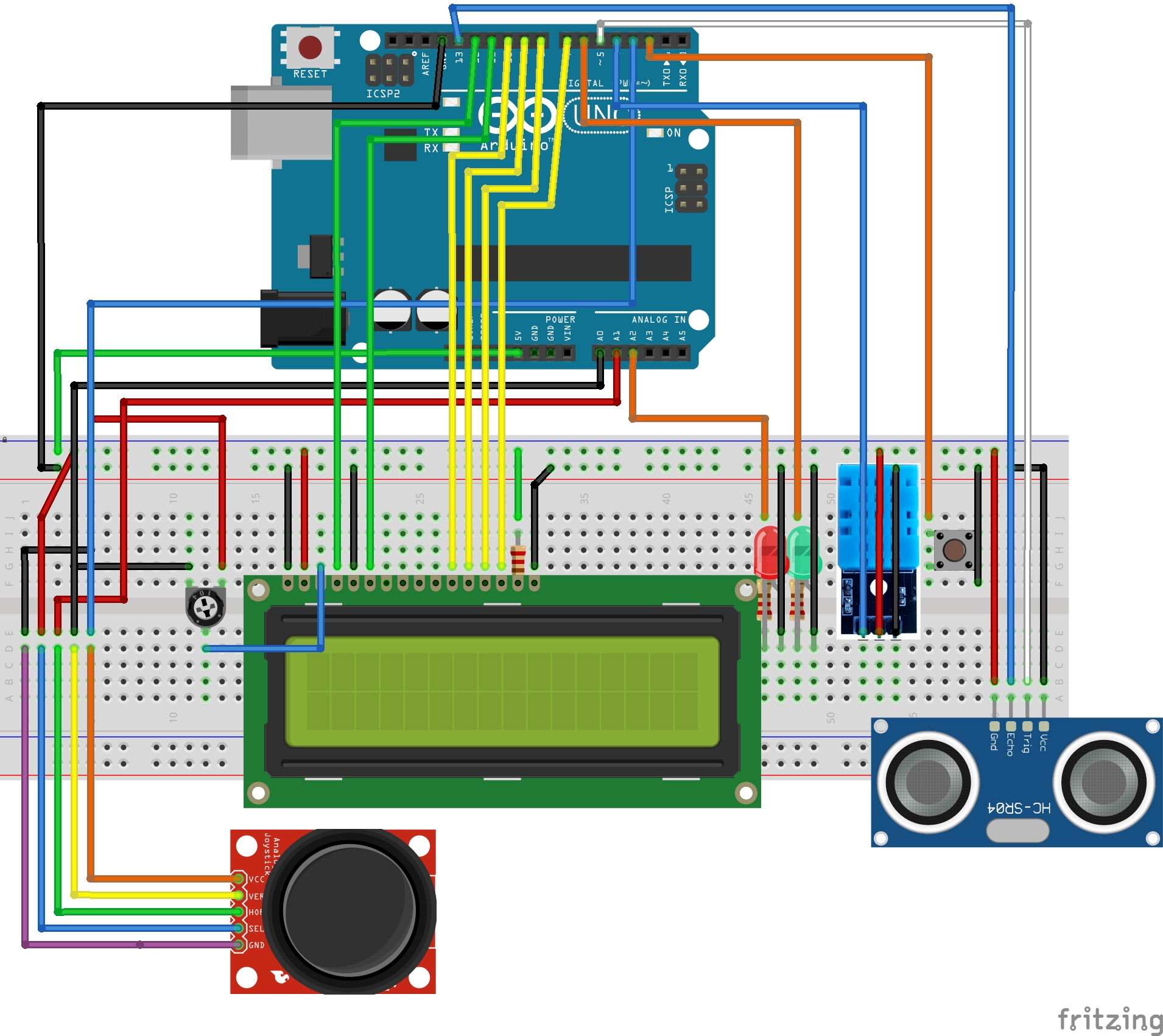
Este blog se centra en la descripción de una maquina expendedora realizada con Arduino UNO, concretamente con el kit Elegoo UNO R3.
La maquina se centra en el funcionamiento de maquina expendedora de café, pero cuenta con una estructura general compatible con ampliaciones,
o modificaciones de su uso, ya que se basa en un FSM(Finite State Machine).
Hardware
Introducción
En vez de realizar el código de manera estricta e intrínseca para una maquina expendedora de café, se ha estructurado de manera generalizada para que
solamente realizando cambios en sus estados la maquina cambie de comportamiento. Para ello todas las funciones de los sensores están encapsuladas en funciones
intrínsecas a su comportamiento, o threads dedicados a ellos, por ello si queremos ampliar los estados de la máquina y en ellos usar distintos sensores se puede realizar, llamando
a las funciones pertinentes o los threads pertinentes.
Threads:
LedThread
getCounter()
resetCounter()
IncrementLedThread
resetBrightness()
UltraSound
getPulseTime()
getDistance()
resetDistance()
Dht11
getHumidity()
getTemperature()
Functions:
joystick_x()
joystick_y()
Interruptions:
jy_button()
pressed_button()
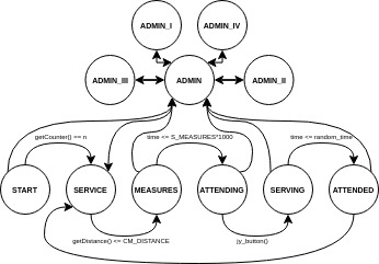
Estados de FSM
START: Estado inicial donde la máquina se está cargando.
Transición: Después de mostrar el mensaje de carga y cuando el contador de LedThread llegue a 3, pasa a SERVICE.
SERVICE: La máquina espera la presencia de un cliente.
Transición: Si el sensor ultrasónico detecta un cliente a una distancia menor a CM_DISTANCE, la máquina pasa a MEASURES.
MEASURES: Estado donde se muestran las medidas (temperatura y humedad).
Transición: Después de mostrar las medidas, pasa a ATTENDING cuando pasa S_MEASURES*1000.
ATTENDING: Estado donde se muestra el menú de café para que el cliente elija.
Transición: El cliente selecciona el café con el joystick (arriba o abajo), si presiona el joystick la máquina transita a SERVING.
SERVING: Estado en el que la máquina prepara la bebida seleccionada.
Transición: Después de un tiempo aleatorio de preparación (entre 4-8 segundos), la máquina pasa a ATTENDED.
ATTENDED: Estado final donde se indica que la bebida está lista para ser retirada.
Transición: Después de que el cliente retire la bebida, cuando pasa S_DRINK*1000, la máquina vuelve a SERVICE.
ADMIN: El menú de administración donde se pueden ver los datos de los sensores, los segundos de la placa o modificar precios.
Transición de llegada: Manteniendo el botón más de MIN_S_ADMIN * 1000.
Transiciónes: Dependiendo de la opción seleccionada en el menú, puede pasar a ADMIN_I, ADMIN_II, ADMIN_III, o ADMIN_IV, seleccionando con joystick,
Transición de salida: Manteniendo el botón más de MIN_S_ADMIN * 1000.
ADMIN_I a ADMIN_IV: Sub-estados del menú de administración donde se pueden ver o modificar configuraciones.
Transición: De vuelta a ADMIN si se navega hacia atrás, o a SERVICE si se mantiene el botón más de MIN_S_ADMIN * 1000.
EXIT: Estado de salida, sin uso.
Caracteristicas Destacadas
1. Estado START
En el estado de arranque nos encontramos una función start_machine(), el cual realiza la representación, en el LCD, de CARGANDO y una serie de puntos que
dan dinamismo a la representación. Lo más característico de este estado es que controlamos el tiempo que tenemos que cargar mediante el parpadeo de un led.
Por ello hemos arrancado un thread LedThread que en run() solamente hace la labor de cambio de estado de HIGH a LOW, y cada vez que hace una transición cuenta 1
a su contador interno, y llamando a su método ledThread1->getCounter() vemos cuantas veces a parpadeado y si tenemos que cambiar de estado.
2. Movimientos Joystick
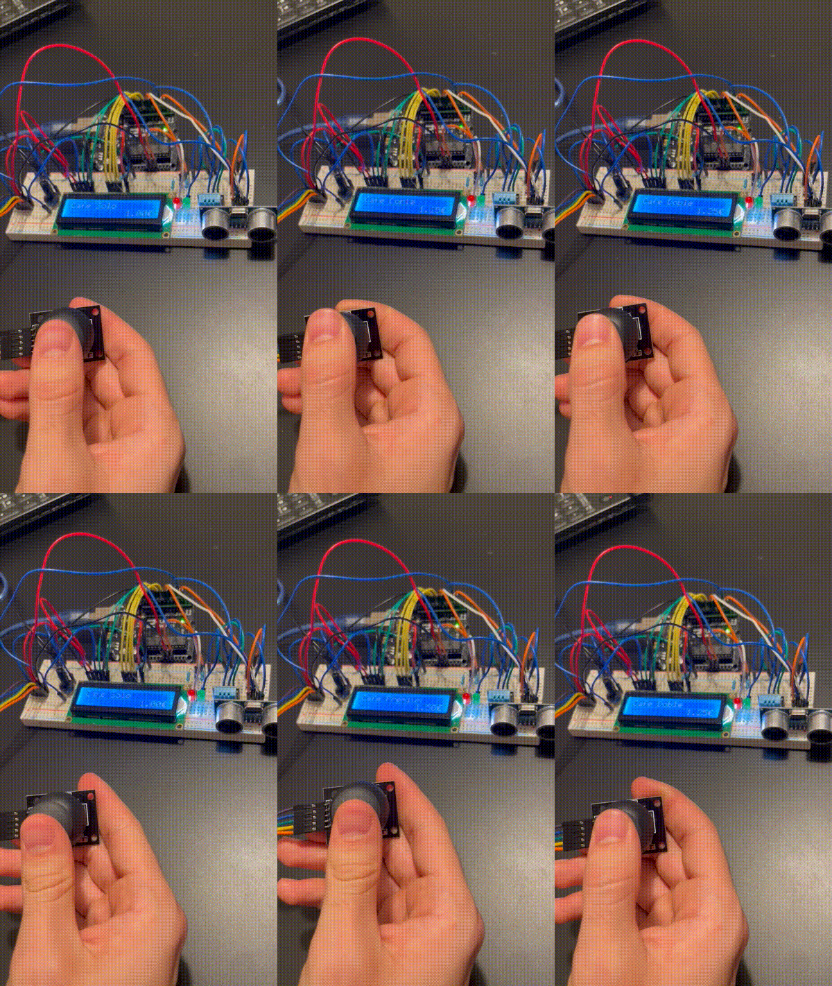
El joystick cumple un papel principal en la máquina, la comunicación cliente maquina, gracias a el el cliente puede “comunicarse” con la maquina. Al ser un rol tan importante
he tratado de darle el máximo dinamismo posible, por ello tenemos dos funciones principales joystick_x()/ joystick_y() las cuales marcan la dirección del movimiento siendo
arriba y abajo gracias al eje y, y derecha e izquierda gracias al eje x.
// 1 is up, -1 is down, 0 no moved
int joystick_y() {
  int index = 0;
  int vy = analogRead(joy_y_pin);
  if (vy > 800) {
    return 1;
  } else if (vy < 300) {
    return -1;
  }
  return 0;
}
// -1 is left, +1 is right, 0 no moved
int joystick_x() {
  int index = 0;
  int vx = analogRead(joy_x_pin);
  if (vx > 800) {
    return 1;
  } else if (vx < 300) {
    return -1;
  }
  return 0;
}
Además para darle el dinamismo deseado podemos scrollear hacia arriba y abajo manteniendo el joystick en una dirección, pero para ello hay que
realizar esperas entre movimiento y movimiento ya que si no al iterar tan rápido no seriamos capaces de controlarlo. Por ello cuando usamos
el joystick, principalmente en nuestro caso arriba y abajo joystick_y(), hacemos realizamos esperas definidas en S_JOY_REACT*1000.
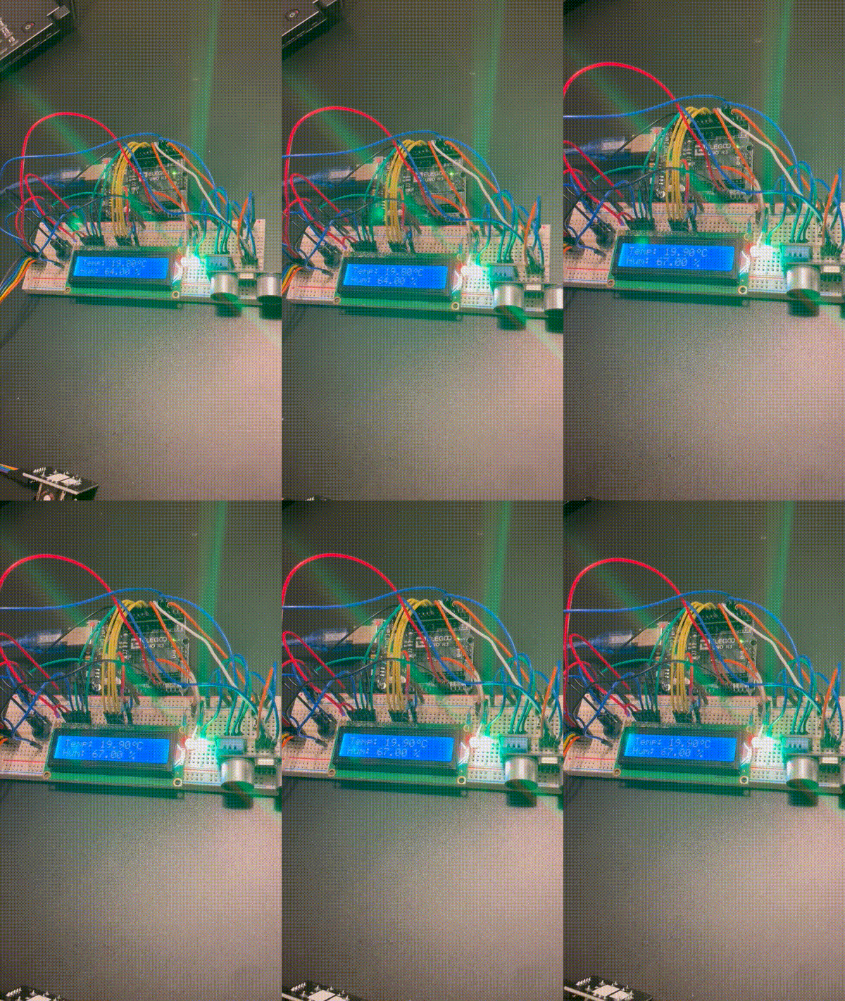
Para tratar este sensor hemos tenido que importar una librería, DHT sensor library dedicada a nuestro sensor, el sensor DHT11. Esta librería nos facilita el uso
del sensor mediante un tipo de dato DHT(DHTPIN, DHTYPE), que al pasarle el pin y el tipo de sensor, en nuestro caso DHT11, ya nos establece el sensor. Cuando llamamos
a su método begin() lo configuramos de la manera correcta, permitiéndonos su uso. A partir de ahí podemos realizar las llamadas sus métodos dht->readHumidity() y
dht->readTemperature().
Para facilitar su uso, esta integrado todo en una clase Dht11, que se trata de un thread, el cual al arrancarlo y seleccionar su intervalo de recopilación de datos
el sensor guardará los datos en unos atributos de su clase, y para extraer su valores están los métodos:
getHumidity()
getTemperature()
4. Sensor De UltraSonido
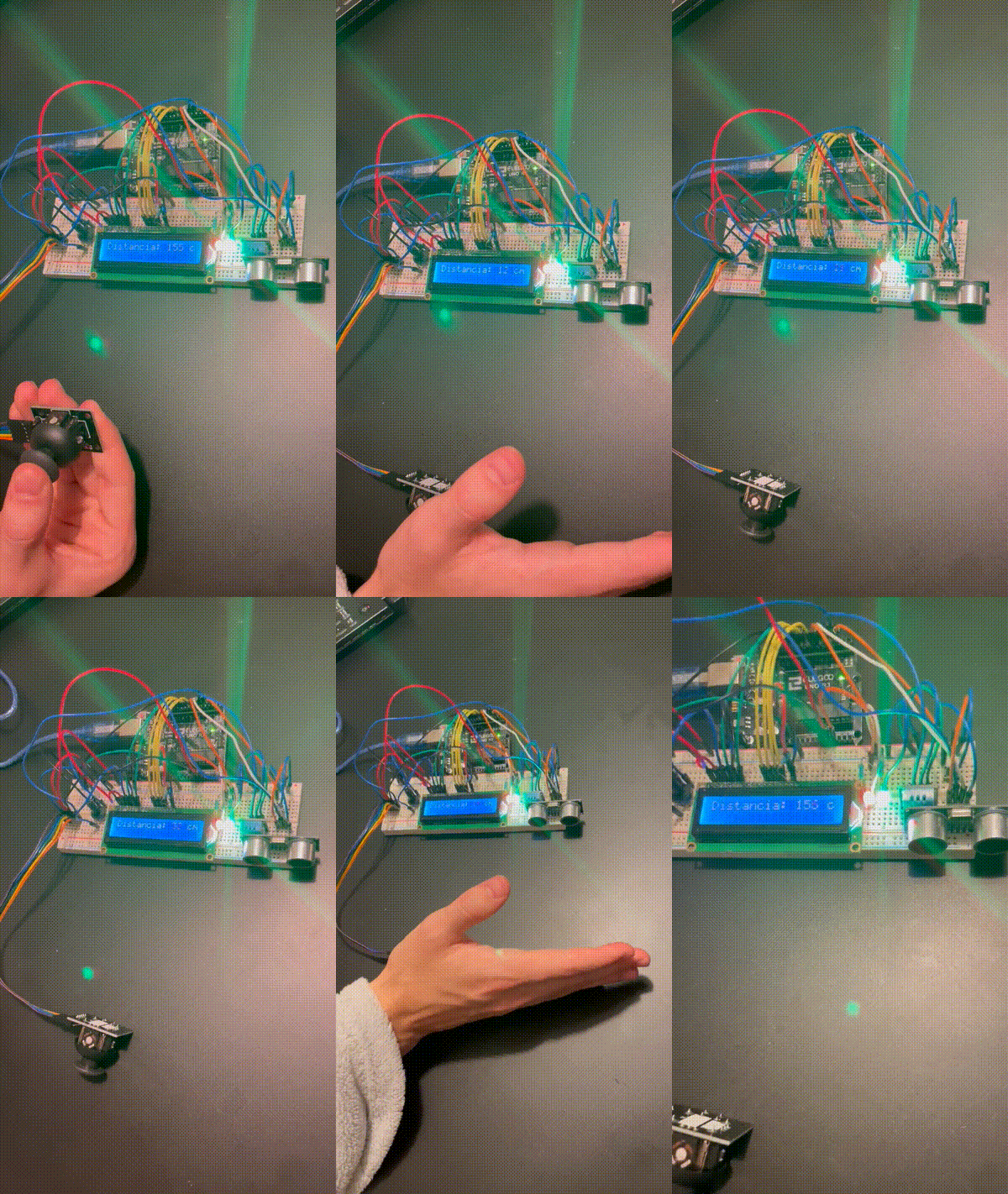
El funcionamiento del sensor ultrasónico HC-SR04 se basa en dos pines principales: Trigger y Echo, que se encargan de emitir y recibir las ondas ultrasónicas, respectivamente. Para su operación, se envía un valor HIGH al pin Trigger durante 10 microsegundos para emitir una onda ultrasónica. Luego, se cambia a LOW para dejar de emitir. Posteriormente, se utiliza la función pulseIn(ECHOPIN, HIGH) para medir el tiempo que tarda la onda en regresar, lo que corresponde al ancho de pulso.
Con este valor, se puede calcular la distancia al objeto utilizando la fórmula:
distancia = (t_pulso * 0.034) / 2
Donde:
t_pulso es el tiempo medido en microsegundos.
0.034 es la velocidad del sonido en el aire (en cm/µs).
El factor 2 se debe a que el tiempo medido es el de ida y vuelta de la señal.
5. Modificación De Precios
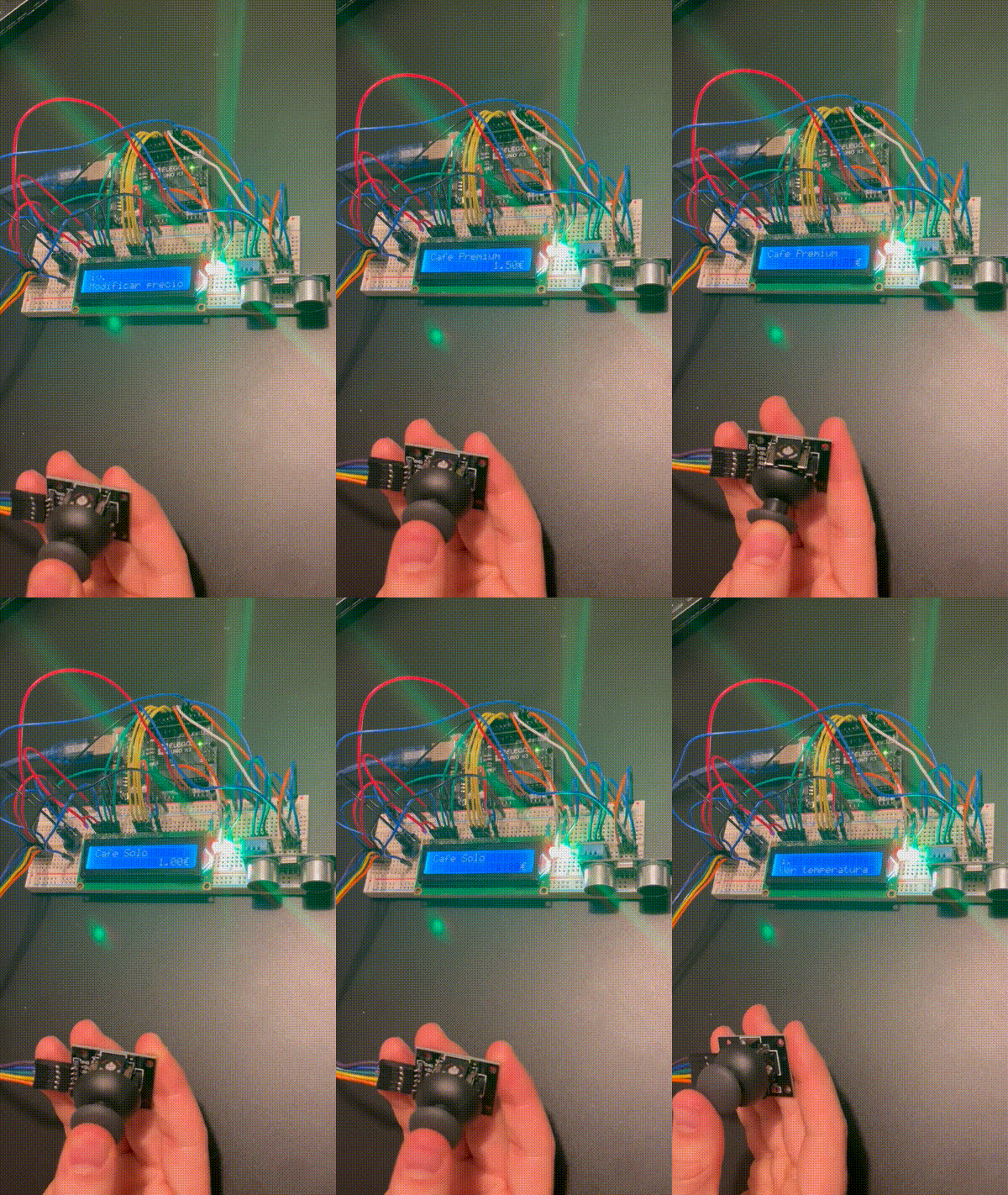
Cuando se arranca el programa hay un precios predefinidos pero estos precios pueden ser modificados en el estado ADMIN_IV, al cual se accede desde ADMIN.
En este “subestado” del ADMIN, se hace uso de todos los ejes del joystick:
x: Para movernos hacia atrás(izq), ya sea volver a ADMIN o volver a la selección del café que queremos modificar su precio, o hacia adelante(drch) para seleccionar el apartado precio y modificarlo.
y: Para scrollear arriba y abajo, y así elegir el café correspondiente o modificar subiendo bajando su precio.
Además cuenta con dinamismo de imagen, ya que al seleccionar el precio este parpadea como símbolo de elección.
6. Interrupciones De Botones
La maquina cuenta con dos interrupciones, tanto el botón del joystick como el botón común. Ambos gestionados mediante circuito PULL_UP, nos marcan
si se ha presionado o no los respectivos botones. Estos botones solo tienen uso en distintos estados, ya sea:
Joystick button: Solo tiene uso para seleccionar el café deseado, y seleccionar la información deseada del ADMIN.
Common button: Su uso es durante todo el código, y dicta si se accede a la función de ADMIN, o se sale, o si has avanzado más del estado SERVICE para poder salir y esperar a un cliente.
Videos
Vending Machine:
Conclusión
El uso de threads para organizar las tareas de manera más limpia y estructurada facilita el entendimiento del código y distribuye las funciones de forma eficiente. Aunque las operaciones de los threads sean secuenciales, la concurrencia que ofrecen da la impresión de que se ejecutan simultáneamente, mejorando la percepción de fluidez del sistema.
Además, el uso de interrupciones en los botones permite que la máquina nunca esté detenida ni realizando espera activa para comprobar estados, ya que las propias interrupciones se encargan de gestionar los cambios necesarios de manera eficiente.
Finalmente, el empleo de un watchdog proporciona una solución robusta para evitar bloqueos de la máquina. Gracias a la facilidad que ofrecen los threads y su funcionamiento concurrente, es posible utilizar tiempos de comprobación más cortos, minimizando el uso de funciones como delay() y mejorando la reactividad del sistema.
.gif)

.gif)